gtgbvf
Central
Arizona Chapter
Module Wiring

Track Buses and Feeders
Our module wiring consists of two 14 AWG twisted pair cables for each
of the two tracks installed on a module. There are also two 20 AWG
twisted pair cables to support two types of lighting power;
incandescent and LED.
The two track bus cables are connected between modules by four wire
Molex connectors. These bus cables have either a male or female
connector on one end, and the other ends are connected to the terminal
block mounted in the center of the module as seen in Figure 1 below.
The same is true for the lighting bus cables,
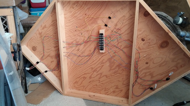
Figure 1. Bus wires and track feeder wires connect to the central
terminal block.
Feeder wires are soldered to either the track rail joiners or the track
center post connector. On each module edge which connects to another
module, the track bus and lighting bus cable Molex connectors will have
opposite gender. This design prevents the bus wires from accidentally
being connected incorrectly. In figure 1, on the right module
connecting edge, the track bus cable connector is male and the lighting
bus cable connector is female. The opposite is the case on the left
module connecting edge. In figure 1, the bottom of the module is the
inside edge.
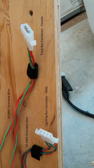
Figure 2. Cable connectors on the right module connecting edge as seen
from below.
Figure 2 is a close up of the bus cable Molex connectors at the
module's right (seen from the bottom) connecting edge. The track rail
bus, consisting of two twisted pairs of 14 AWG wire, one pair for each
track, are terminated with a female Molex connector. Looking at the
Molex connector, you can see there is a red wire at the end of the
connector which has the V shape. This will be connected to the outer
track's outer rail feeder (also colored red). See Figure 4 below. A red
wire is always at the V shape end of the Molex connector whether male
or female.
Figure 3 shows which pins are placed in the connector casings. The pin gender MUST match the casing gender.
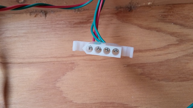
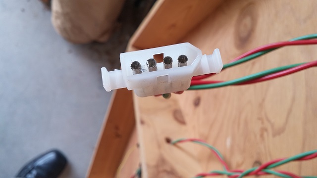
Figure 3. Pin gender must match the casing gender.
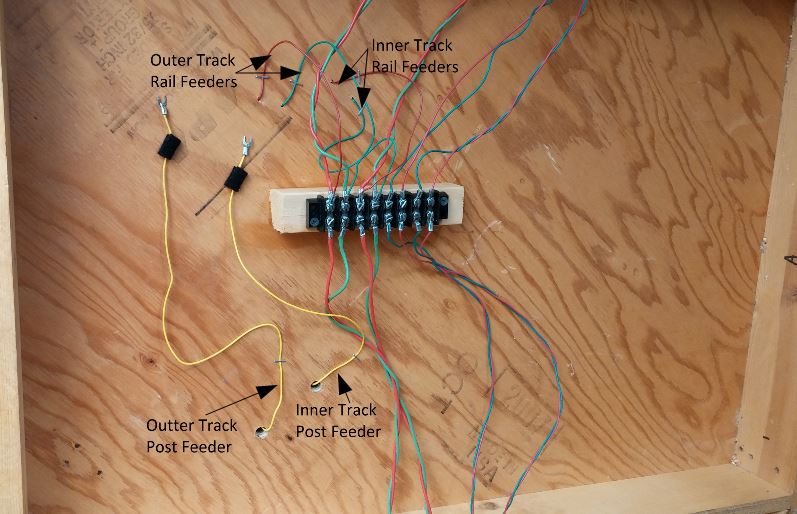
Figure 4. Track feeders connecting to the terminal block.
The track feeders (20 AWG) are connected to the rails by soldering
them to the rail joiners, and to the center posts at the connector at
the bottom of the rails at the end of a track. Red wires are connected
to the outer rails of each track, and green are connected to the inner
rails of each track. Soldering the feeders to the rails at the
rail joiners is straight forward. I use a very fine resin core solder;
the kind used for electronics work. It melts quickly, and doesn't
require the soldering iron to be on the joiners long enough to melt the
ties.
The yellow wire for the center post feeder is more difficult to connect
to the track if the track is already installed. To do this, you must be
very careful when boring out a hole from beneath the module surface. I
used a very sharp 9/16" steel bit. Wood bits won't work because the
tips are too long and will destroy the rails when they burst through
the wood. I first drilled two small holes on either side of the rail at
a rail joint from the top of the module so I would know where to drill
the larger hole from beneath. Then, with a variable speed drill, bore
out a small amount at a time, watching the depth so you will know about
when the bit will break through. The break through should just eat a
bit of the cork roadbed out. Then using an X-acto knife, carve out the
cork until you can see the shiny metal of the center post connector.
You should now apply some solder to the center post connector to "tin"
it. With a yellow feeder wire that has been stripped of about 3/8"
insulation, tin that also with a bit of solder. You can now place the
feeder wire into the hold until it touches the center post connector,
apply heat with the soldering iron for a few seconds, then remove the
heat, holding the wire for several seconds to let the solder solidify.
Give the wire a slight tug to make sure it's been soldered firmly. Now
with a multimeter on the Ohms setting, or any other device you have to
show continuity, make sure your feeder wire is making electrical
contact with only the center
post connector. You should only have continuity between the yellow
feeder and any of the center posts on the rail. Use a staple gun to
staple the feeders near when they exit the bottom of the module. This
provides strain relief and prevents the wire from being accidentally
jerked from its solder connection.
All feeder wires are solid as opposed to stranded.
Switching between DC and AC
You can make either or both of the rails carry DC or AC depending on
how the feeders are connected. In the figures here, both tracks are
connected to carry DC. If you wanted to switch a track to AC,
simply move the red feeder for that track at the terminal block
from the red bus wire to the green bus wire, and connect the yellow
feeder that services that track to the red bus wire. See figure 6. The
AC configuration will then have the yellow feeder wire connected to the
red bus, and the red and green feeders connected to the green bus.
Remember to do this for every module! The connecting tracks will
also have to be changed from DC type to AC type.
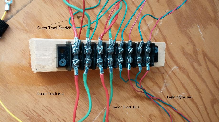
Figure 5. Terminal block wiring configured for DC on both tracks.
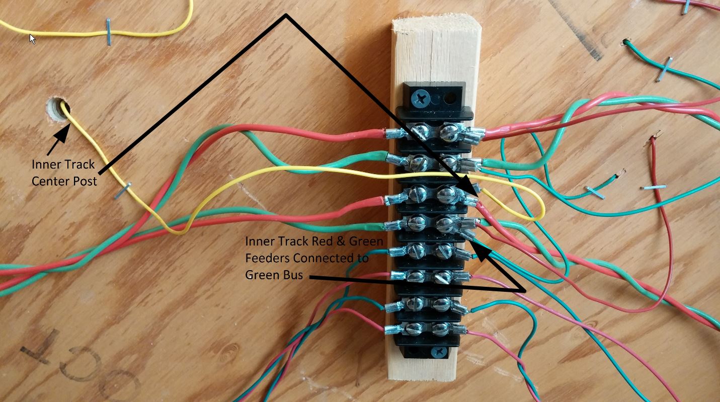
Figure 6. Terminal block wiring configured for DC on outer track, and
AC on inner track.
The terminal block provides a convenient place to make connections that
need to be secure, but not necessarily permanent. The wood block is
mounted using a wood glue held in place with screws until the glue sets
in about 24 hours. Use care when tightening the terminal screws so you
don't break the plastic.
Lighting Buses and Feeders
There are two lighting buses. One for 5 volt power and the other for 16
volt power. The 5 volt bus is typically used for LED lighting, and the
16 volt bus for incandecent lighting. The 5 volt bus should be DC since
they are considered DC devices. The 16 volt bus could be either AC or
DC. For LEDs and the 5 volt bus, it is important that the color of the
feeders be connected consistently so each light gets the correct
polarity. If the LEDs don't light, reverse feeders as they
connect to the lighting bus.
Bus Power Box
One of the corner modules has the power panel mounted on it. The panel
has large phono jacks for track bus power, and smaller jacks for
lighting bus power.
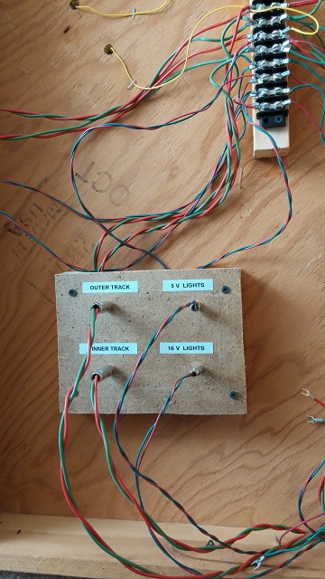
Figure 7. Power panel.
Wires from the jacks feed the appropriate buses at the terminal block.
The wires connected to the plugs are connected to the appropriate power
sources. (Note, in the photo the labels have a bluish tint. In fact,
they actually have a white background.